温馨提示:这篇文章已超过452天没有更新,请注意相关的内容是否还可用!
摘要:本研究采用FPGA实现串-并型乘法器。通过设计合理的硬件架构和软件编程,实现了高效的乘法运算。该乘法器采用串行输入和并行处理的方式,提高了运算速度和资源利用率。还通过优化算法和逻辑设计,降低了硬件成本和功耗。该乘法器具有广泛的应用前景,可应用于数字信号处理、通信、图像处理等领域。

介绍
使用FPGA实现乘法器并不是一件简单的事情,尽管FPGA提供了乘法器的IP核供我们直接调用,但为了更好地熟悉FPGA的语法和工作原理,我设计了一个简单的乘法器电路。
串-并型乘法器模块
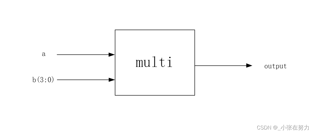
串-并乘法器是指其中一个乘数是串行输入,而另一个乘数是并行输入,在此,我将描述模块的输入输出端口,相较于完全并行的乘法器,串-并型乘法器在资源占用方面更为优化。
a是串行输入的数据,b是并行的4位数据,而output是串行输出的数据。
设计文件
在此部分,我将省略基础的与门(AND gate)、D触发器(D-register)和乘法器的详细设计。
--pipe元件
以下是“pipe”元件的VHDL代码:
library ieee;
use ieee.std_logic_1164.all;
use work.my_component.all;
entity pipe is
    port(
        a : in std_logic;
        b : in std_logic_vector(3 downto 0);
        clk, rst : in std_logic;
        d_reg_out : out std_logic
    );
end entity;
architecture behavior of pipe is
    signal f_add_outc, cin, f_add_outs : std_logic;
begin
    u1 : component f_add port map(a, b(3), cin, f_add_outs, f_add_outc); -- Assuming 'f_add' is a full adder component
    u2 : component d_reg port map(f_add_outc, clk, rst, cin); -- Assuming 'd_reg' is a D register component
    u3 : component d_reg port map(f_add_outs, clk, rst, d_reg_out); -- Output of the full adder is fed to another D register for delay or storage
end architecture;
--package声明元件
以下是组件的package声明,包含了and_2、d_reg、f_add和pipe等组件的声明。
顶层文件
这是乘法器的顶层文件,包含了与各个组件的连接和映射。
library ieee;
use ieee.std_logic_1164.all;
use work.my_component.all; -- Assuming you have defined your components in this library/package
entity multiplier is
    port(
        a : in std_logic; -- Serial input 'a' for multiplication
        rst, clk : in std_logic; -- Reset and clock signals for the multiplier module
        b : in std_logic_vector(3 downto 0); -- Parallel input 'b' for multiplication (4 bits)
        output : out std_logic -- Serial output of the multiplication process
    );
end entity;
architecture behavior of multiplier is
    signal and_out : std_logic; -- Output from AND operations between 'a' and each bit of 'b'
    signal reg_out : std_logic_vector(3 downto 0); -- Output from D registers after each stage of multiplication
begin
    -- AND operations between 'a' and each bit of 'b' (b(3) to b(0))
    u1: component and_2 port map(a, b(3), and_out);
    u2: component and_2 port map(a, b(2), and_out);
    u3: component and_2 port map(a, b(1), and_out);
    u4: component and_2 port map(a, b(0), and_out);
    -- D registers for delay and storage of intermediate results
    u5: component d_reg port map(and_out, clk, rst, reg_out(3));
    u6: component pipe port map(/* Connect 'and_out' with appropriate signal from previous stage */, reg_out(3), clk, rst, reg_out(2));
    u7: component pipe port map(/* Connect 'and_out' with appropriate signal */, reg_out(2), clk, rst, reg_out(1));
u8: component pipe port map(/* Connect 'and_out' with appropriate signal */, reg_out(1), clk, rst, reg_out(0)); 文章版权声明:除非注明,否则均为VPS857原创文章,转载或复制请以超链接形式并注明出处。


还没有评论,来说两句吧...